I changed the i2c section in VOCORE.dts to:
- Code: Select all
      i2c@900 {
         compatible = "link,rt5350-i2c", "ralink,rt2880-i2c";
         reg = <0x900 0x100>;

         resets = <&rstctrl 16>;
         reset-names = "i2c";

         #address-cells = <1>;
         #size-cells = <0>;

         pinctrl-names = "default";
         pinctrl-0 = <&i2c_pins>;

         status = "okay";
      };
I did not add i2c support in kernel_menuconfig
In make menuconfig I added kernelmodules:
- Code: Select all
   kmod-i2c-core
   kmod-i2c-ralink
(I think they were already present btw)
I added Makefile (
https://dev.openwrt.org/browser/package ... s/Makefile) to
package/i2c-tools/Makefile Then I did
- Code: Select all
make menuconfig
and selected
Utils
i2c-toolsafter flash and reboot, I do
- Code: Select all
insmod i2c-dev
and see the device /dev/i2c-0
Then I connected a YL-40 (
https://brainfyre.wordpress.com/2012/10 ... le-review/) module
to 3v3 on pin PB18 (lower right corner, marked 3v3), GND, DATA, and SCLK
Then when you do
- Code: Select all
i2cdetect 0
you expect only 0x48 to be present, but almost all adresses are present.
It seems something to do with pull-up, so:
Added a 4K7 pull up parallel to the 10K on YL-40, but that did not give any improvement.
Lowered VCC for YL-40 by putting diode inline, did not help too.
Any ideas?
Is there a second function of the pins that need to be disabled?
Is there more that I can check?
Concerning my thoughts about SDATA/SCLK swap:
The sch.pdf shows SCLK next to RESET in the black interface section,
but in the pdb.pdf it is SDATA next to RESET.
When I follow the tracks on the red layer of the pcb.pdf, and see the pinnumbers in
RT3530.pdf Table 1-2 196-Pin BGA Package Diagram Top View (right portion)
I see that sch.pdf seems to be right and pcb.pdf seems to be wrong.
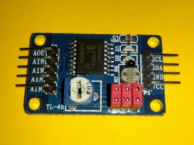 . It has the resistors on the board, no?