Page 1 of 4
VoCore Breakout Board
Posted: Tue Dec 30, 2014 8:33 pm
by Greenwire-Elektronik
Ready to ship - visit our
shop and buy your breakout board!
Re: VoCore Breakout Board
Posted: Wed Dec 31, 2014 5:53 am
by brandonhead
Any possibility to add more 3.3v and 5v output? That will be convenience while interfacing a lot of different sensors.
Re: VoCore Breakout Board
Posted: Thu Jan 01, 2015 4:18 am
by Greenwire-Elektronik
Will check for it tomorrow - I might reconsider the design and give it a proper power supply to supply vocore and I/O devices.
Re: VoCore Breakout Board
Posted: Thu Jan 01, 2015 11:22 am
by Ton
Also add a 3rd pin for GND to the I2C and UART 'connector'. That would be much easier in use.
Re: VoCore Breakout Board
Posted: Thu Jan 01, 2015 12:33 pm
by Greenwire-Elektronik
Yep - i want to add gnd to every function group
Re: VoCore Breakout Board
Posted: Thu Jan 08, 2015 4:32 pm
by Greenwire-Elektronik
The prototype pcbs have arrived - just waiting for pin headers to start testing.
Re: VoCore Breakout Board
Posted: Fri Jan 09, 2015 3:14 am
by Vonger
Looks good

Re: VoCore Breakout Board
Posted: Fri Jan 09, 2015 8:20 am
by Greenwire-Elektronik
Thanks - btw, it is a pain to get 1,27mm (0.100") headers in germany - do you have a good source?
Re: VoCore Breakout Board
Posted: Fri Jan 09, 2015 11:39 am
by noblepepper
They are a pain to find anywhere...
In the U.S.A, Mouser has some, details for the 4 position sockets are below.
Mouser Part #:
855-M52-5000445
Manufacturer Part #:
M52-5000445
Manufacturer:
Harwin
Mouser claims to have a location in Munich but they may not carry the same items there.
For the others (pins and 7 position sockets) I am getting ones in stock with more positions and will cut them down to what I need.
Re: VoCore Breakout Board
Posted: Sat Jan 10, 2015 11:36 am
by Greenwire-Elektronik
I got my pin headers from Reichelt.de - thanks for the mouser link, i will check it.
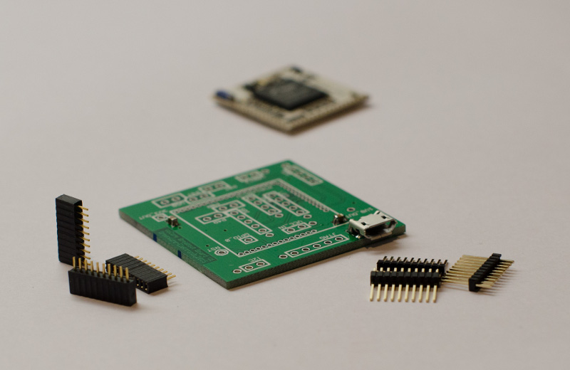
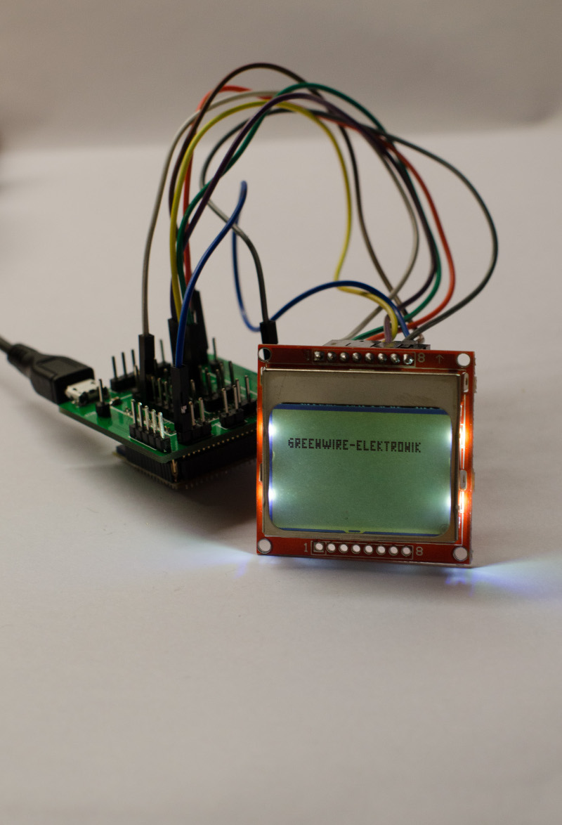
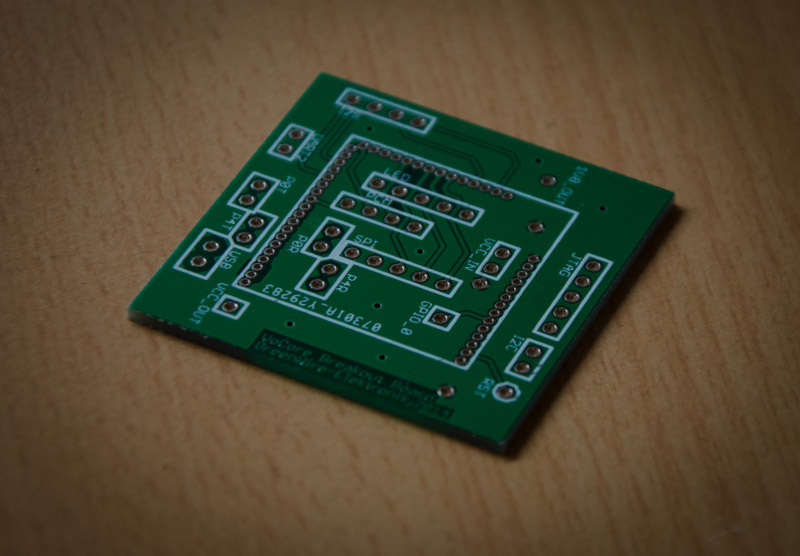
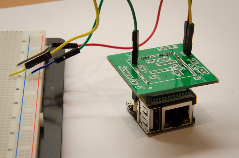
Meanwhile a frech set of pictures:
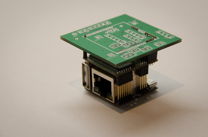
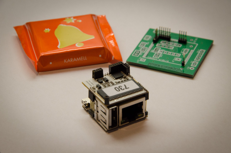
I found some problems - the DRAM is to large so it is (without reworking the pinheader case) not possible to solder a pin header in the adjacent row. Also in the corner where G#14 and GND are positioned the gap between them was designed to small on the VoCore - you can only solder one of the two pins. For the DRAM problem i might just cut a bit of the case of the pin headers so that they are getting smaller. Also there are collisions of the pin headers with the USB socket, but cutting the pin header helps.